Difference between revisions of "Panoramic Stitching and WebRTC Streaming on NVIDIA Jetson"
(→Resource Scheduling) |
|||
| Line 55: | Line 55: | ||
To access these units GStreamer is used. In a GStreamer pipeline each processing accelerator is abstracted in a GStreamer element. The following table describes the different processing stages, the HW accelerators used for them and software framework used to access them. | To access these units GStreamer is used. In a GStreamer pipeline each processing accelerator is abstracted in a GStreamer element. The following table describes the different processing stages, the HW accelerators used for them and software framework used to access them. | ||
| + | |||
| + | {| class="wikitable" | ||
| + | |- | ||
| + | ! Processing Stage !! Amount !! HW Unit !! Software Framework !! Notes | ||
| + | |- | ||
| + | | Camera || Example || Example || Example || Example | ||
| + | |- | ||
| + | | Decoder || Example || Example || Example || Example | ||
| + | |- | ||
| + | | Projection || Example || Example || Example || Example | ||
| + | |- | ||
| + | | Image Stitching | ||
| + | |- | ||
| + | | Crop and Scaling | ||
| + | |- | ||
| + | | Encoder | ||
| + | |- | ||
| + | | WebRTC | ||
| + | |- | ||
| + | |} | ||
| + | |||
Besides this configuration, it is important that the cameras have little to none tangential or radial angles. | Besides this configuration, it is important that the cameras have little to none tangential or radial angles. | ||
Revision as of 20:46, 22 July 2022
This wiki serves as a user guide for the Panoramic Stitching and WebRTC Streaming on NVIDIA Jetson reference design.
Overview
The demo makes use of a Jetson AGX Orin devkit to create a 360 panoramic image in real time from 3 different fisheye cameras. The result is then streamed to a remote browser via WebRTC. The following image summarizes the overall functionality.
1. The system captures three independent video streams from three different RTSP cameras. Each camera captures an image size of 3840x2160 (4K) at a rate of 30 frames per second. Furthermore they are equipped with a 180° equisolid fisheye lens. The cameras are arranged so that they each capture perspectives at 120° between them. The following image explain graphically this concept.
As you can see, the cameras, combined, cover the a full 360° field of view of the scene. Since each camera is able to capture a 180° field of view, and they facing 120° apart from each other, there is a 60° overlap between them. This overlap is important because it gives the system some safeguard to blend smoothly the two images. See the section below for more considerations regarding the physical setup of the cameras.
2. The Jetson AGX Orin receives these RTSP streams and decodes them. These images are then used to create a panoramic representation of the full 360° view of the scene. The different HW accelerators in the SoM are carefully configured to achieve processing in real-time. The image below shows an example of the resulting panorama.
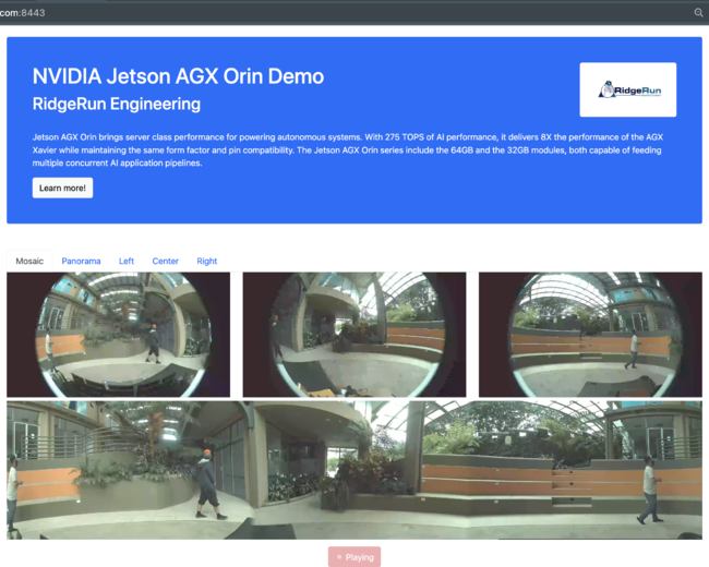
3. Finally, the panorama is encoded and streamed through the network to a client browser using WebRTC. Along with the panorama, the original fisheye images are also sent. The client is presented with an interactive web page that allows them to explore each camera stream independently. The following image shows the implemented web page in mid-operation.
System Description
While the system should be portable to different platforms of the Jetson family, the results presented in this guide were obtained using a Jetson AGX Orin. More specifically, the configuration used in this demo follows the information detailed in the table bellow.
| Configuration | Value |
|---|---|
| SoM | Jetson AGX Orin NX |
| Memory | 64GB |
| Carrier | Jetson Orin AGX Devkit |
| Camera protocol | RTSP |
| Image size | 4K (3840x2160) |
| Framerate | 30fps |
| Codec | AVC (H.264) |
Resource Scheduling
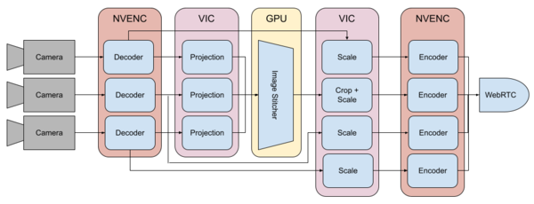
To maintain a real-time operation of steady 30fps, this reference design makes use of different hardware modules in SoM. The following image shows graphically how the different processing stages of the system were scheduled to different partitions in the system.
To access these units GStreamer is used. In a GStreamer pipeline each processing accelerator is abstracted in a GStreamer element. The following table describes the different processing stages, the HW accelerators used for them and software framework used to access them.
| Processing Stage | Amount | HW Unit | Software Framework | Notes |
|---|---|---|---|---|
| Camera | Example | Example | Example | Example |
| Decoder | Example | Example | Example | Example |
| Projection | Example | Example | Example | Example |
| Image Stitching | ||||
| Crop and Scaling | ||||
| Encoder | ||||
| WebRTC |
Besides this configuration, it is important that the cameras have little to none tangential or radial angles.


