Equirectangular Projection
WORK IN PROGRESS. Please Contact RidgeRun OR email to support@ridgerun.com if you have any questions. |
| Image Stitching for NVIDIA®Jetson™ | |
|---|---|
 | |
| Image Stitching for NVIDIA Jetson Basics | |
|
|
|
| Getting Started | |
|
|
|
| User Guide | |
|
|
|
| Compiling OpenCV for Image Stitching | |
|
|
|
| Examples | |
|
|
|
| 360 Video | |
|
|
|
| Performance | |
|
|
|
| Contact Us |

|
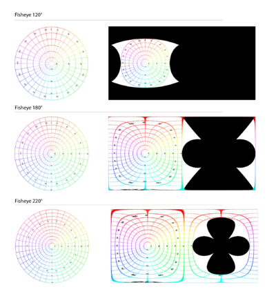
You need to create an equirectangular projection from each fisheye image. Even though the fisheye only covers a limited angle of view of the real world, the corresponding equirectangular projection image corresponds to the 360 degrees but will have black areas.
The relationship between the fisheye image and the equirectangular projection can be determined geometrically, we are not going to get into details, but you can visualize it in the figures below. As you can see, the region projected in the equirectangular frame will change according to the aperture. For the equirectangular projection of a fisheye of 180 degrees or less half of the image is totally black and doesn’t provide any relevant information, so that memory could be discarded to save resources.
You need to know that a fisheye to equirectangular projector converts the fisheye image where the real-world verticals are curved to actual vertical lines in the equirectangular image and the horizon is converted to an horizontal line. If the resultant equirectangular projection doesn’t look like this you should adjust the projector configuration to accomplish these results.
In a real-world scenario, the fisheye lenses will not be located on the same optical axis and will not have the same characteristics. So to adjust the equirectangular projection to this imperfect setup, you need to define to the projector the fisheye lens characteristics: aperture, radio, and center. Also, you can configure the fisheye rotations to adjust the optical axis, it is assumed that the camera is looking over the Y axis, so the Y rotation works to roll the fisheye lens as if you grab the lens front and rotate your hand. The X-axis is at the side of the camera, so if you change the rotation over this axis you can correct the fisheye tilt angle. And finally, the Z axis is up over the camera and works to pan the fisheye camera over the horizon, this property is rarely used for the 360 stitcher since the stitching stage is in charge of adding the offset to move the equirectangular images horizontally to match them.
RidgeRun implemented a GStreamer element that performs the equirectangular projection from an RGBA image. The element allows the adjustment of the projector setup through properties. The details of the element and how to use it can be found in section X.
360 Stitcher
Finally, when you have the equirectangular image per camera, you can use RidgeRun’s cuda stitching solution to stitch them together. The purpose of the stitching is to align the equirectangular images, blending the overlap regions to produce a single 360 frame.
The stitcher used for 360 frames generation is the same used for regular rectilinear stitching, the difference will be the type of input image and the configuration required for each case. As you may know, the stitcher supports putting together any amount of inputs, however for a 360 solution 2 or 3 fisheye cameras will be enough to cover the 360 world area around them. If your setup uses 2 cameras back to back it is recommended to use lenses of at least 190 degrees even though 180 degrees would be enough to cover the area. These 10 extra degrees allow the stitching to have a blending zone to work with, producing smoother transitions between the images. The overlap region will depend on your camera array configuration and the angles of view of the cameras you are using.
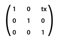
To work with the stitcher you need to define a homography configuration, this is nothing else than a description of the relationship between the images. The homography configuration is defined in pairs of images, where one image is the reference and the other one is the target, the target will be transformed to match and adjust to the reference image using a homography matrix. In the case of fisheye 360 stitching, the projector already made most of the transformations required to match the images, and at this stage, only an offset definition will be required. For cameras aligned in the same plane, you only need to define the horizontal offset corresponding to the reference equirectangular image size minus the overlap region that will correspond to the angular distance between the cameras. In general, for 360 stitching your homography matrix will look like the following:
One of the challenges of stitching together 360 equirectangular videos is the parallax effect, which corresponds to the difference in the apparent position of an object viewed from different points of view and lines of sight. To have perfect stitching with no parallax effect your cameras should be in the same position which is physically impossible, so there cannot be perfect stitching in the real world. But you can adjust the projections and stitching configuration to have a nice blending at a certain depth, meaning a certain distance from the camera's array. However, if you adjust to some distance probably objects closer or further from that distance will present parallax issues. Also, the parallax will be determined by the distance between the cameras, smaller cameras closer together will be closer to the ideal setup where both cameras occupy the same space so the parallax effect is small but for bigger cameras further apart the parallax effect will be more noticeable.


