Full Body Pose Estimation for Sports Analysis - Pose Correction
WORK IN PROGRESS. Please Contact RidgeRun OR email to support@ridgerun.com if you have any questions. |
Contents
Introduction
The pose correction module is intended to map the trainer and traineeT sequences to a 3D space when needed and after that, compare them to obtain the differences. Additionally, it generates the corrections and displays them in a 3D GUI for the user to explore them interactively.
How it Works
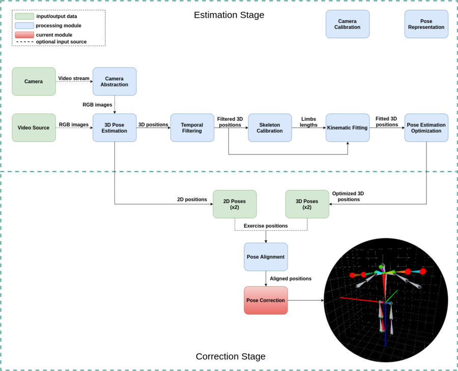
The different steps involved in this module are shown in the next flow diagram:
Next we will get deeper into each of the submodules.
3D Representation Generation
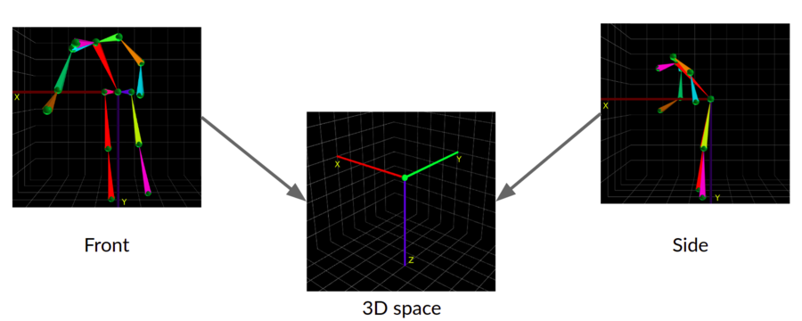
In order to provide the movement correction it is required that this one is represented in 3 dimensions to ensure an accurate feedback. If the inputs are in 2D it is impossible to give a recommendation related to forward or backward movements due to the lack of depth of the image. Here we will use the front and side auxiliar views prepared in the alignment preprocessing in order to generate the 3D representation. As seen in the next image what we do is to map all the X and Y positions of the front views to the X a Z axes of the 3D space and then the X positions of the side views to the Y axis of the 3D space.
Movement Differences Computing
Once we have the trainer and traineeT sequences in 3D space, we proceed to compute the differences between them in each frame. At this point, both sequences are temporally aligned, therefore each frame from the trainee sequence has its corresponding frame in the traineeT sequence. The differences between movements are computed by a common subtraction in each of the joints and also in each of the axes since we have to provide feedback in the three directions.
Text Correction Generation
Next, when we already have the computed differences between both sequences, we compare them against a given threshold and if they are higher than the threshold then we produce a text correction with the form of Move the X joint to Y, where X and Y are the name of the joint and the direction of the correction, respectively. The thresholds for the correction should be defined taking into account the units of the input data, because 2D inputs are in pixels, while 3D are given in centimeters. In this case, it does not matter if the original input was in 2D and now it has been moved to a 3D representation, the units are still the same of the input.
3D GUI Visualization
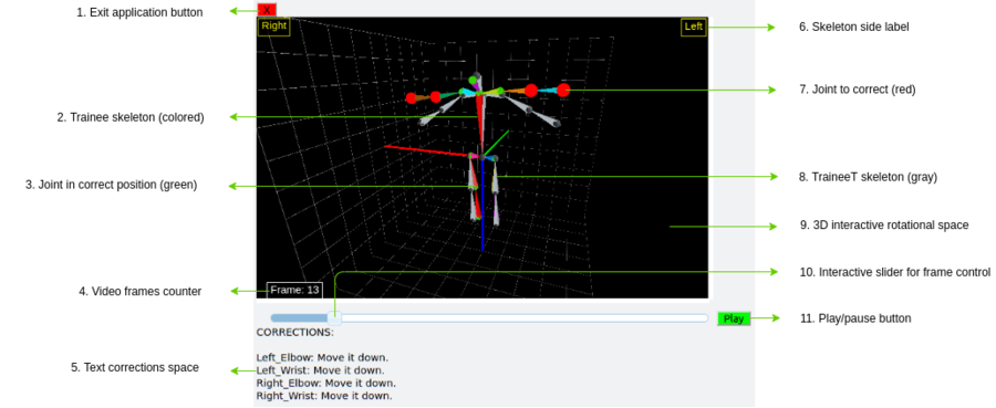
Finally, the last stage is about showing the correction result to the user in a way in which they are able to check the part of the exercise that was performed incorrectly. To ease this process we provide not only the text corrections, but also a 3D visualization with the trainee skeleton on top of the traineeT skeleton to take it as a visual reference. This visualization is generated using the skeleton visualization submodule of the pose representation library. In this graphic user interface there are interactive components for the user to move forward or backwards in the video as pleased. In the next figures you can see an example of this visualization with each of its graphic components and a demonstration of how it is used.


